Wednesday, December 1, 2010

Copy DriveWorks Pro 7 Projects

By Michael Jolley

As a DriveWorks Administrator, there are many times where you may want to work on a project, but do not want to expose your development work to end users. At the same time, you still need end users to be able to generate specifications without interruption. There are a couple of ways to achieve this in DriveWorks 7 Pro.

This first method involves having a Test Group (database) and a Production Group. In this case, there is a great Help topic accessible from the web-based documentation: http://docs.driveworkspro.com/HowToCopyAProjectIntoAnExistingGroup.html
This will take you through, step-by-step, how to copy your project from one group to another existing group. The process is similar to what the DriveWorks 6 Deployment Tool would do for you. Although this is a manual process, it is quite straightforward without the black magic of the now defunct deployment tool.

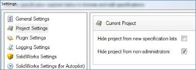
While the aforementioned process works well, there is often times no real need to have a Test Group. With the onset of DriveoWorks Pro 7, we can choose to hide a project from non-administrators while we debug or develop it. While a project is open for edits in DW Administrator, simply change the settings for the project to "Hide project from non-administrators."


Now you can work on your test project without worrying about someone accidentally running specifications on it. When you get your test project ready for others to run, just uncheck this box.

Obviously, there will be times when you need to edit a project that end users are already using. Assuming that you cannot take the project offline while you make your edits, you may want to copy the project within the same group. The process is very similar to copying between groups. Naturally, there will be a few differences versus the two-group approach.

To copy the project, simply follow the procedures within the help file link that I mentioned above, but you can skip the steps related to importing the required components. This will mean that both projects will use the same SolidWorks files. With the new, copied project, change the project setting to hide it from non-administrators. Now you can modify your project till your heart's content.

When you are finished with the edits, you could turn off the non-admin access to the new and turn it on for the old. If you named your new project creatively, this might be all you have to do. For example, if my original project was called "Window Frame" and my copied project is named "Window Frame v2," then everyone will know that it is an updated copy. Of course, you could always delete the old and rename the new to match the original name so no one knows how many iterations you're going through. Naturally, you will need to make sure that neither project is in use prior to deleting and renaming.

Tuesday, November 16, 2010

Rapid Prototyping Saves the Day for Dad

One of the greatest things about working here at TriMech (outside of Bagel/Donut Day on Friday) is the exposure to a wide variety of tools. From the Entire SolidWorks Suite of tools to the 3D Printers and PDM Systems, we get to work with a lot of cool technology. Professionally, it's great exposure. Personally, it can bring some benefit too.
Case in point, My daughter has a battery-powered truck she inherited from her older brother.

She was driving the truck around on Saturday when I heard it making an awful crunching noise. Apparently, it's been doing that for a while. I did some investigative work and determined the problem to be a stripped gear in the gearbox. It was missing 7 teeth along the outside. Thinking that I couldn't readily run down to Lowe's or Home Depot and pick up a power wheels rear end gear, I thought I would utilize the tools around me to find a solution to this devastating problem.


On Sunday, my 8-year old son and I took the bad gear and sat down with a pair of calipers; we modeled up a replacement gear utilizing SolidWorks 2011 and saved the file out as an STL. On Monday morning, I used the Fortus printer we have at TriMech to run a replacement gear. We happened to have a blue color cartridge in the machine, which makes the picture showing the replacement gear even easier to visualize.


The Blue gear was inserted into the train and it fit beautifully on the first try. I added a little grease, sealed it back up and had the truck running within 15 minutes. Although this was a personal use of the technologies we sell and support at TriMech, it's very indicative of the way we should be utilizing existing technology as Engineers to make better products and to cut down on LONG production cycles.

And now the kids think I can fix about anything...added bonus.


Friday, October 22, 2010

Free is for ME!

PART 1 OF 2 BY RYAN ZECK

Please write the check out to me, as I am about to show you some programs that will save you so much time you won’t believe it! Okay, now that I have your attention, the programs are free (but donations are accepted!). I love to learn new programs especially if they will help me do my job quicker and more efficiently so from time to time I look around the web and find a simple program to fill a specific need.

My hope is for these few programs to help you in several areas of YOUR job and to impress your friends or co-workers. In no way am I saying these programs run flawless as there is no software that can promise that. I have been using most of these for a while. Some of them work better than others, but I can’t promise they will work as I describe them as they are just freeware.

The first program I use EVERY day. In fact, it is the first program I use when I boot up my laptop. It is called Speed Launch. You can find it on the Microsoft Labs Website where all the Beta programs are shown. You may want to poke around on that website to find other programs to fit your own needs. I did test the “forgotten attachment detector” without success. However, the Speed Launch program has worked very well for me as I start up four different programs at one time. Some days I teach people how to use SolidWorks and have to start it along with my 3D Connexion program and my EPDM vault.


To explain it a bit further, it is a way to open a document, program, or website with the flick of a finger. Check it out here: http://www.officelabs.com/projects/speedlaunch/Pages/default.aspx

The next useful program is “Search Commands,” also found on the Microsoft Office Labs website. So let’s be honest, when I started using Office 2007 (excel or word), I was a bit confused on where all my buttons went that I always used. This was also echoed by many of my friends who felt the same confusion and frustration. Let it be known that Microsoft also realized this problem and you can download “Search Commands” to help assist you to find the button you desire. It is a simple tab on the ribbon where you get a box to search like you would on the internet. As you type the buttons available change and narrow to what is most relevant. Pretty cool if you ask me, you should check it out here: http://www.officelabs.com/projects/searchcommands/Pages/default.aspx


Synergy is a program a co-worker found and told me about. At first I didn’t think it was really needed but after using it, hands down one of the most cool things you can do with a computer….or really two computers. How many people still have their old computer? It still works, right? But you don’t have a KVM switch to get them to talk to each other, plus those switches are NOT free. So to use both of those computers you have to keep both keyboards and mice on the desk. I’m not sure about you, but in my opinion having to switch mice is kind of a pain.

Synergy takes this to a new level, as long as those two computers are networked, you can have one mouse and one keyboard that controls both computers with nothing more than a small program running. You do need to have the old monitor to make this work though.
Not only do they have a version for Windows 32 and 64bit, but they also have one for Linux, and Mac.

Find this program here: http://synergy-foss.org/pm/projects/synergy/tabs/welcome
So in Part 1 we talked about Speed Launch to get things started, Search Commands to keep us going and help find lost buttons, and Synergy to make use of our two computers and to impress friends! Next time we will take a look at a few other programs.


Feel free to email me at rzeck@trimech.com or find me on Linked In at http://www.linkedin.com/in/ryanzeck


Wednesday, September 29, 2010

Design Tips for Turned Parts

By Mike Waller, Atlanta

As a SolidWorks Instructor with a background in manufacturing, I often get questions that are based as much on general manufacturing process principles as they are on SolidWorks design techniques. I always like to share this type of information because I hate to see designers get beat up by fussy machine shop operators because the way they designed their part doesn’t lend itself to the manufacturing process being used. One manufacturing process that is often misunderstood by 3D designers is turning, which is the name of the process by which parts are created on a lathe.

Although the typical designer will never need to use a lathe, it is important to understand the needs of a lathe operator so that you can convey your design intent in a meaningful and easily understood way when your parts are being produced by a turning operation. In case you are unfamiliar with it, turning is a general term used to describe the process of making parts on a lathe. You will also hear the term “turning center” used to describe full CNC controlled lathes. While we’re on the subject, from my experience, you should always avoid using the word “lathe” as a verb, as good machinists typically are very particular about terminology, and you might get a wrench thrown at you if you ask the wrong machinist to “lathe” a part. That would be like a SolidWorks professional being asked by a machinist to “CAD” something. You probably wouldn’t like it.

The first point that I would like to make involves the stock size. Whenever possible, avoid designing turned parts that will require a full-length reduction in diameter from standard stock sizes for the material being specified. An example is low carbon steel round bar. Since round bar is commonly available from US suppliers in fractional inch increments, it is often possible to avoid extra cost by designing around those standard stock sizes. For example, if the tolerance on the largest diameter of your part is not so tight that the stock supplier tolerances would not work, significant cost can be avoided by specifying standard stock size for the outer diameter. In other words, if a part’s max diameter isn’t otherwise critical and could just be “about” ¾ inch, don’t specify oddball diameters like 0.748”. That seems like a simple concept, but I often see designers that for whatever reason are working in mixed unit environments, and never notice that the tightly toleranced 19mm rod size they specified will cause the machinist to turn down the full length of a ¾” round bar to arrive at the final size they need. If instead, the designer specified 0.75” and the tolerance required for the part wasn’t excessively tight, there is a good chance that the machinist would start with ¾” round bar from a supplier like Ryerson Metals and since their tolerance for cold drawn, ground and polished carbon steel round bar up to 1” in diameter is +0.000/-0.001”, no further work would have to be performed for the overall diameter of the part. This one point can save extensive setup and hold costs down. An example of the tolerance sizes can be found here on Ryerson’s web page:

http://www.ryerson.com/stocklist/s-1928-Data-Tolerances-CF-Carbon-Bars.html.

The second area that I see a lot of designers overlook is with the design of shoulders on turned parts that engage into matching holes. Because it is nearly impossible to turn a square corner on a lathe, and since square corners introduce stress concentrations, it is a good idea to put a small, filleted relief groove into any square internal corners. This is especially important when a shoulder diameter is being used as an insertion stop for a hole and pin part that must mate together with sliding or press fits. The image below shows such a relief.


Even if the turned down shoulder diameter on your part doesn’t engage into a hole, it is still a good idea to avoid sharp, square internal corners on turned parts, even if for strength related consideration alone. Try to design in a small fillet in this case. I recommend talking with your machinist to see what radius is preferred, based off available tooling and techniques and design all turned internal corners with a standard fillet size if there is no other compelling reason for a specific radius. This way, standard, off-the-shelf cutters can be used, thus avoiding custom radius sizes. Besides, such a feature is typically not so critical that an exact size is needed, and wouldn’t warrant and custom tool grinds to get a particular radius in.


Finally, all 3D CAD designers working with turned parts should avoid dimensioning turned diameter features with radius dimensions. Diameters are easy to measure with standard metrology tools like micrometers and calipers, and they are also very straight forward for the machinist to achieve during the machine setup. If you put radius type dimensions on a turned part, your machinist will think you’re just one of those “booksmart” designers that has no idea how things are actually made, and you’ll run the risk of the machinist doing various math operations to arrive at the dimensions they need to make your part. Although most machinists are plenty skilled in mathematics to handle such calculations, having them do it is just another place for errors to occur, and should be avoided. I always tell my students that the print for machined parts, regardless of the machining operation, should contain all dimensions necessary to manufacture the part, without doing any math. This concept even works in creating the design intent of your features and sketches in whatever 3D CAD system you use, regardless of the manufacturing process.

This article is by no means a complete set of guidelines for designing turned parts, but it is a brief description of how to avoid some of the major pitfalls that I have seen over the years. Hopefully, it will help you design better parts and gain some credibility with your machine shop team. If you are a designer that creates practical, manufacturable prints, most machinists will respond well and they can often get you out of a jam when you do make the inevitable mistake. Try to understand their needs, and take note when they are explaining why your widget is tough to make. They usually know a heck of a lot about their trade, and making their life easier whenever possible will save your company money.

Monday, September 27, 2010

Top 10 Uses for the 'Shift' Key in SolidWorks

by: Eman Kim
It seems like the 'Ctrl' key gets all the attention when running SolidWorks. I thought it be fun to focus on the unsung keyboard command, the 'Shift' key. Here are the Top 10 uses for the 'Shift' Key in SolidWorks in no particular order.

10. Move Aligned Views Together.
Aligned Drawing views will usually move along the alignment of their parent view. If you'd like to move a view and all other views aligned to that view together as a single selection, hold down the 'Shift' key with your click-and-drag.

9. Select a Range of Items
Like Windows, while holding the 'Shift' key you can select a range of items in the Feature Manager Tree. Select the first and last item you wish to select and the items in-between will also be selected.

8. Collapse Items
Quickly collapse all items in the Feature manager tree by selecting 'Shift'-'C'. Can be helpful if your Assembly tree navigation is getting out of hand and you need to get back to the top!

7. Zooming In
You can zoom out from the centroid of your model using the 'Z' key. 'Shift'-'Z' reverses this behavior and zooms you into the centroid of the model. Also, holding down the 'Shift' key while you click and drag with your middle mouse button will zoom you in and out of the centroid of your model

6. Rotating 90 degrees
Holding the 'Shift' key with your arrow keys will allow you to rotate the model 90 degrees in any direction.

5. Return to Last View
If you've ever miss rotated or moved out of a desirable view into one you're not to pleased with you can use 'Ctrl'-'Shift'-'Z' to get you back to your previous view.

4. Rotate Routing Components
When initially applying connectors, clips, and other routing systems components you can rotate them using the shift and left and right arrow keys. Of course the file will need a rotational axis in the feature manager tree to rotate the component.

3. Moving a Model Dimension Between Views
If you have a model dimension in one view you'd like to move to another, you can simply drag the dimension to the new drawing view while holding down the shift key. The dimension should just reattach itself to the appropriate edges after the drop.

2. Select Transparent Items
When working with a mixture of transparent and solid objects, selecting a desired edge or face can be difficult. By default, if a transparent object is over a solid object, SolidWorks will want to select the solid object. You can use the 'Shift' key to override this behaviour so that SolidWorks will select which ever item is closest to you regardless of their transparency.

1. Dimensioning Arcs
When dimensioning arcs, SolidWorks will alway default to the center of the arcs. Holding the 'Shift' Key, SolidWorks will snap to the closest min/max(quadrant) position when dimensioning arcs.

Next time, we'll focus on the Top 10 Uses for the 'Ctrl', 'Alt', and 'Tab' keys in SolidWorks! Catch you again.

Thursday, September 16, 2010

Dimension Printers with Dan Genovese


Since coming to work at TriMech, I’ve learned a lot about both the CAD industry and the rapid prototyping industry as well. Since becoming the “Expert” on 3-D Printers at TriMech, I have learned a lot about this technology. These machines are capable of a lot, but when it boils down to it, the technology itself is pretty easy to discuss. At a very high level, the benefits of 3D Printing include, but are not limited to the following:

• You can quickly produce prototypes of your models to see if they work as you expect!
• You can modify your model, print it again, and make sure it is ready to be produced!
• You can save valuable time and money whereas previously you might have to send your models off to expensive prototyping shops!

These are the most important benefits and selling points for the Dimension printers that we sell. Every time I go visit a customer who has a Dimension printer, I hear stories about how great of an investment their printer has been. From medical device companies able to put a prototype of a product into a surgeon’s hand before producing it to other industries producing low-volume production runs, it seems like everyone who buys one of these machines gets a great amount of use out of it.

Despite the obvious popularity of the machines, I find myself wondering where the process could go from here- how it could be expanded. A lot of people have seen the Dimension clip with Jay Leno where he uses a printer to create molds to build replacement parts for his old, no longer manufactured cars (if you haven’t seen it, check it out here, it’s actually pretty good). This clip is a great example of taking this technology to the next level beyond “just producing a prototype”

Most engineers know that despite the usefulness and power of CAD software like SolidWorks, sometimes you just can’t get the look and feel right for your designs, especially if the shape is more “organic”. But what if you already had a mock-up of a product, created by hand, and you needed to carry that concept through to actual production? With 3DScanning technology, you could scan the model and then send the part right into your CAD system. From there, you could use SolidWorks to create the mold around the part. In the last and final step, you would use the Dimension printer to create the mold for production runs, or simply to produce “X” number of low volume production parts from the original scan.

I’ve just scratched the surface of what can be accomplished with a Dimension 3D Printer. I think we are at a point in this product’s life cycle very similar to 20-30 years ago with Plotters. Back then, large plotters were sometimes viewed by engineering departments as “nice to have”. Pretty soon, their adoption rates made it pretty obvious that to generate the drawings from all electronic files we were rapidly creating, the plotter was going to be a necessity. This is the simple evolution of a next step, we’ve just added the third-dimension to the plot. Pretty soon, I believe these printers will be integral to every engineering department and down the road, companies will wonder how they ever functioned without them.

Thursday, August 26, 2010

SolidWorks and Apple: The Love Hate Love Relationship

by: Eman Kim
Today, it’s not uncommon for me to visit a client and see that they have proudly managed to run SolidWorks on a Mac. After all, the only thing that could rival the loyalty of a SolidWorks user would be that of an Apple products user. Besides being a zealous user base, there also seems to be this culture of cool and superiority that characterizes both Apple's products and users. You see it in everything from the way their products are marketed to how Apple users prominently display their shiny new toys. With this much cultural clout, you’d figure it would be natural that SolidWorks would have jumped on the bandwagon and released a version of their software that would natively run on Apple’s platform.

Don’t hold your breath.

Below is a short history of SolidWorks and Apple’s 15 year love hate relationship.

1995 –SolidWorks 95 is born
As long as SolidWorks has been around, Mac users have attempted to run SolidWorks on a Mac. In the early days, the only way to run SolidWorks on a Mac was to emulate Windows. Users quickly discovered the inherent problems with running SolidWorks® this way. Unlike Word or Excel, SolidWorks® is truly a performance and resource demanding application. OpenGL graphic driver support was nearly non-existent in emulated environments. This, along with the limited amount of memory in early Macs hampered both performance and stability.

2001 – OS X
Apple made a dramatic change to their operating system and moved to a UNIX-like based OS X operating system. Later releases proved OS X to be a very capable and robust platform with a far stronger memory management system. This allowed for greater stability when running emulated environments, but users still needed to sort through the slew of hardware compatibility and performance issues when running SolidWorks.

2005 – SolidWorks eDrawings© on OS X
Collaborators rejoice! Despite not being able to create content, OS X Tiger users could at least view what their PC buddy was doing in SolidWorks®. What’s interesting to note was that the Mac versions of eDrawings© had features that its PC cousin originally did not have. Advanced print preview options as well as the ability to filter components by name came to the Mac version of eDrawings before finding their way onto the PC.

2006 – Intel, Boot Camp©, and Virtualization
In 2006, Apple Computer® walked away from its longstanding PowerPC platform. But what sent shockwaves through the computing community was Apple’s new relationship with long time hardware rival, Intel Corp. This new partnership meant that both PCs and Macs would contain similar hardware allowing Microsoft Windows to now run natively on a Mac.

To accomplish this, users simply need to use the Boot Camp© utility that comes with OS X Leopard and later OS X operating systems. The drawback with using Boot Camp© is the need to reboot whenever you need to change operating system environments.

In cases where users need to run both operating systems simultaneously, virtualization programs like VMWare Fusion or Parallels Desktop can be used to run Windows in a parallel operating system environment. Unlike earlier emulation software, the current virtualization products no longer need to emulate a PC’s hardware environment. This greatly improves system stability and performance. In regards to SolidWorks, the only sticking spot when running Boot Camp or a virtualized environment is the OpenGL® driver support and higher end graphic functions like RealView. Currently, SolidWorks® and its resellers officially do not support SolidWorks® in either Boot Camp© or a virtualized environment.

2007 - Steve Wozniak at SolidWorks World 2007
Co-founder of Apple Computer, Steve Wozniak was a keynote speaker at 2007's SolidWorks World Event. Though some optimistically speculated that Wozniak was going to announce iSolidWorks during his keynote, we instead got an insightful talk on the importance of synergy between products and their users.

2007 – Drawings Now© on iPhone
The SolidWorks Labs application, Drawings Now© allows users to view drawings via the web. Users simply upload their SolidWorks documents up to the web and anyone can review the documents from a capable browser…including the iPhone’s Safari.

2010 – SolidWorks World 2010 Announcement
Feb 4th, just days away from Valentine’s Day, it seemed like the perfect time for SolidWorks to announce a new partnership with Apple at SolidWorks World. The initial images that emerged during the general session made it appear that SolidWorks was going multi-platform. Later, we learned SolidWorks was instead going platformless as they would be venturing into the world of cloud computing. In short, regardless of your operating system, users would be able to run a cloud version of SolidWorks as a web application. Timetables were undefined and details were sparse, but it did raise a fair bit of excitement and speculation throughout the SolidWorks community about the future of platformless cloud computing.

So there you have it, a short rundown of the long history of SolidWorks and Apple. Aside from SolidWorks in the cloud, it appears the only native platform SolidWorks will run on in the near future will be a Windows based PC one. Sorry Apple users. Businesswise, it doesn’t make a whole ton of sense for SolidWorks to invest hefty development resources into a lone Mac version of SolidWorks. There’s just so much more SolidWorks needs to fix and develop and Apple takes up less than 8% of the computing market space…

though it is a very cool 8%.